
APC Single Phase Uninterruptible Power Supply at Rs 7200/piece in Indore ID 17690129930
The schematic is very simple to implement, and everything is pretty much just the datasheet recommended values—there isn't much to think about for this.. While this is built as a standalone uninterruptible power supply, you can use the concepts within this design to provide a battery backup capability to your own devices. The design.

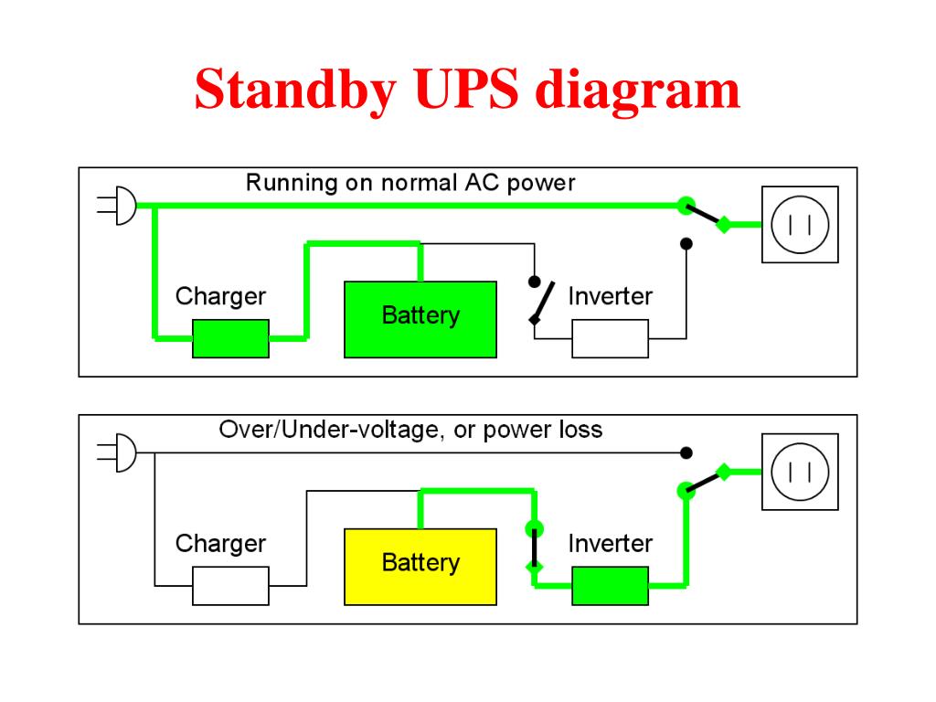
Simplified diagram of offline Uninterruptible Power Supply (UPS)... Download Scientific Diagram
A UPS, or a uninterruptible power supply, is a device used to backup a power supply to prevent devices and systems from power supply problems, such as a power failure or lightning strikes. A UPS can help prevent power supply problems that can often occur on a production site, such as an instantaneous voltage drop and a power failure.

Uninterruptible Power Supply Schematics New Wiring Diagram Image
A UPS or uninterruptible power supply uses batteries and supercapacitors to store electrical energy and delivers this stored electrical energy when the main input power supply fails. However, a typical UPS battery can supply electrical power for a short duration. Hence, UPSs are mostly used as short run time backup power sources for small loads.

Uninterruptible Power Supply UPS Design Notes PAKTECHPOINT
An Uninterruptible Power Supply (UPS) is defined as a piece of electrical equipment which can be used as an immediate power source to the connected load when there is a failure in the main input power source. In a UPS, the energy is generally stored in flywheels, batteries, or super capacitors. When compared to other immediate power supply.
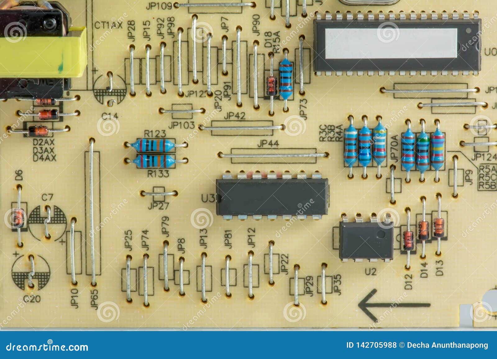
Component of Uninterruptible Power Supply Stock Photo Image of industrial, object 142705988
Design#4: 1kva UPS Design. The last design but by far the most powerful discusses a 1000 watt UPS circuit powered with a +/- 220V input, using 40 nos of 12V/4 AH batteries in series. The high voltage operation renders the system relatively less complex and transformerless. The idea was requested by Aquarius.

Uninterruptible Power Supply Schematics New Wiring Diagram Image
Once utility power returns, the system transfers the load back to utility power without interruption. The UPS can be used in a wide range of commercial power applications. The system provides voltage regulation and protection from power outages. This provides well-regulated power to cover critical loads during sags, surges, or outages.
The Basics of Uninterruptible Power Systems 24x7 Magazine
Figure 1 shows a typical industrial application for an uninterruptible power supply. Here, an industrial sensor is supplied with power. The reliability of the system mainly depends on the power supply of this sensor. A linear charge regulator IC is used to charge a supercapacitor when there is available system voltage.
Simple ups circuit diagram
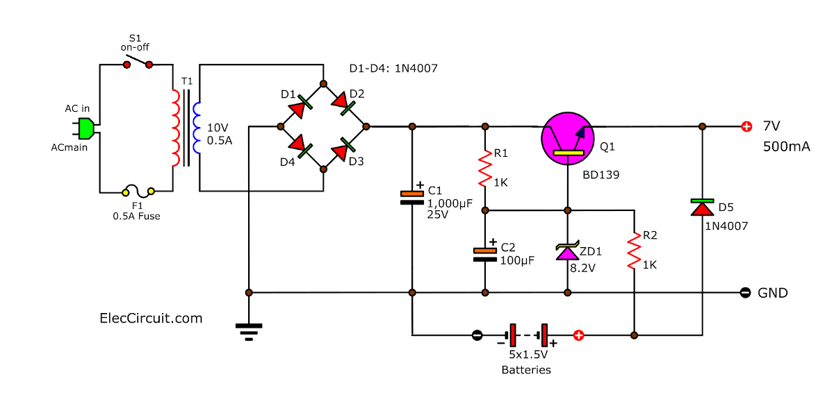
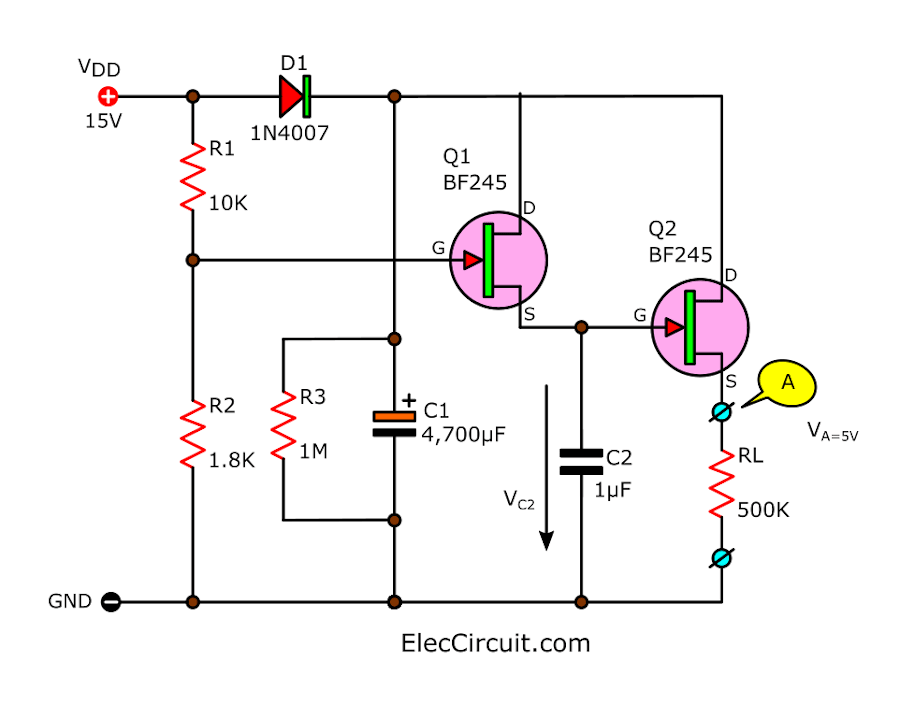
Look at the circuit below. We connect the Backup battery 7.5V (AA 1.5Vx5) with D2 in series, and both across the output terminal. The voltage drop across D2 serves to reduce the voltage level of the power supply down to about 7V (6.8V). Also: 8 ways how to converts 12V to 6V. Small Uninterruptible Power Supply UPS Circuit.
UPS Uninterruptible Power Supply Circuit Diagram
An uninterruptible power supply (UPS) or uninterruptible power source is a type of continual power system that provides automated backup electric power to a load when the input power source or mains power fails.. When power loss occurs, the rectifier simply drops out of the circuit and the batteries keep the power steady and unchanged. When.

UPS uninterruptible power supply circuit diagram
Offline uninterruptible power supply block diagram. The above block diagrams are self-explanatory. The following are the basic differences between them. Online UPS provides protection against overvoltage, undervoltage, main supply voltage waveform distortion, and frequency fluctuation. Offline UPS only provides protection against supply outages.
Uninterruptible Power Supply Schematics New Wiring Diagram Image
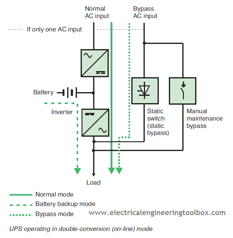
9355 uninterruptible power systems (UPSs) deliver premium levels of efficiency, reliability and flexibility— all in a sleek tower half the size of most competitor units on the market today. This double-conversion, online UPSs resolve all nine common utility power problems and supply clean, continu-ous power to all connected equipment.
3 Simple UPS circuits (Uninterruptible Power Supply) Diagram Eleccircuit
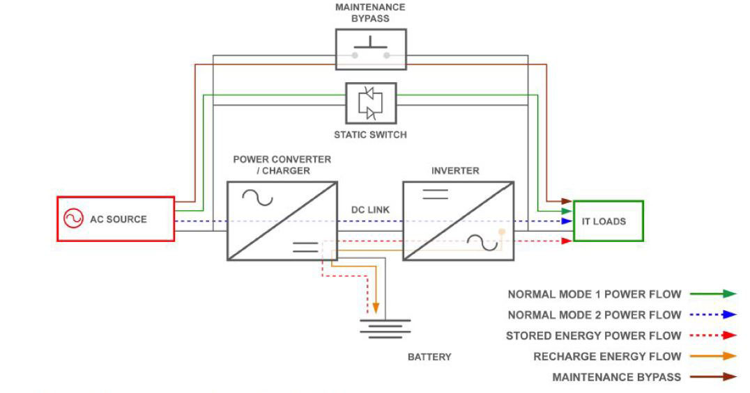
Uninterruptible Power Supply Working. Figure 1 shows the principles of operation of an electronic UPS. Single- or three-phase power is obtained from the power system and is rectified to DC.. The second bypass is a set of manually operated switches that allow the UPS to be disconnected from the circuit for maintenance, which is the bypass.
How UPS (Uninterruptible Power Supply) Systems Works Learning Electrical Engineering
Step 2: The Regulated Power Supply. A UPS must be able to continuously supply the rated current at the rated output voltage, without relying on the back-up battery for assistance. So the first step will be to design a 12V power supply. A good start will be to use the LM317 voltage regulator.

How to Build an Uninterruptible Power Supply for Home Devices Analog Devices
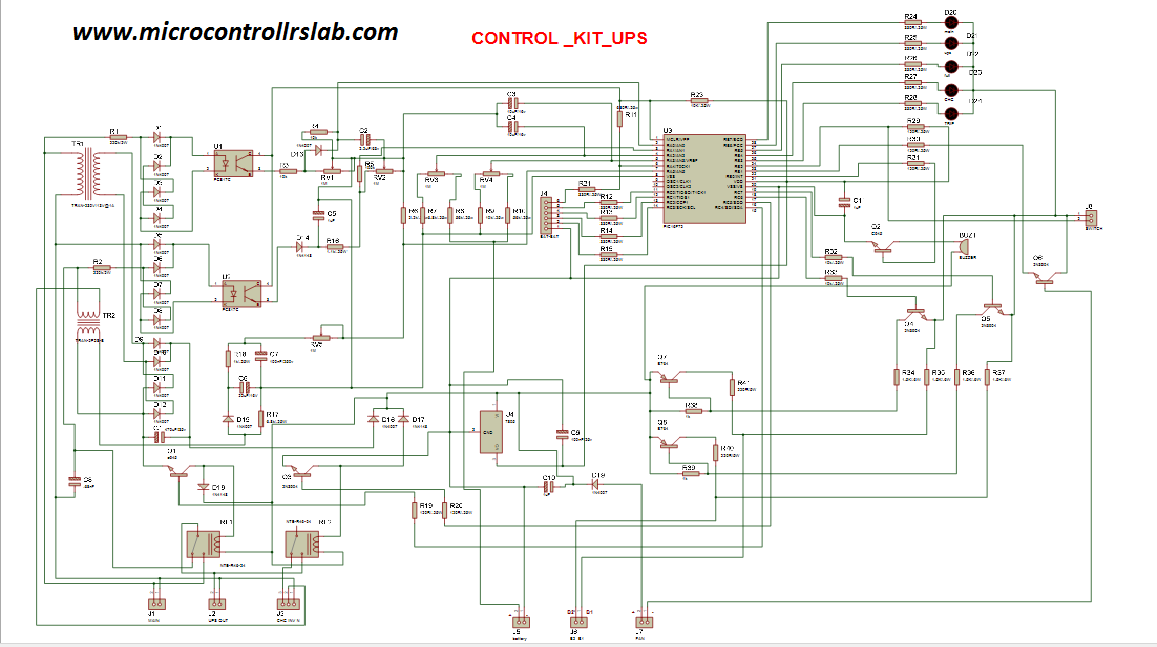
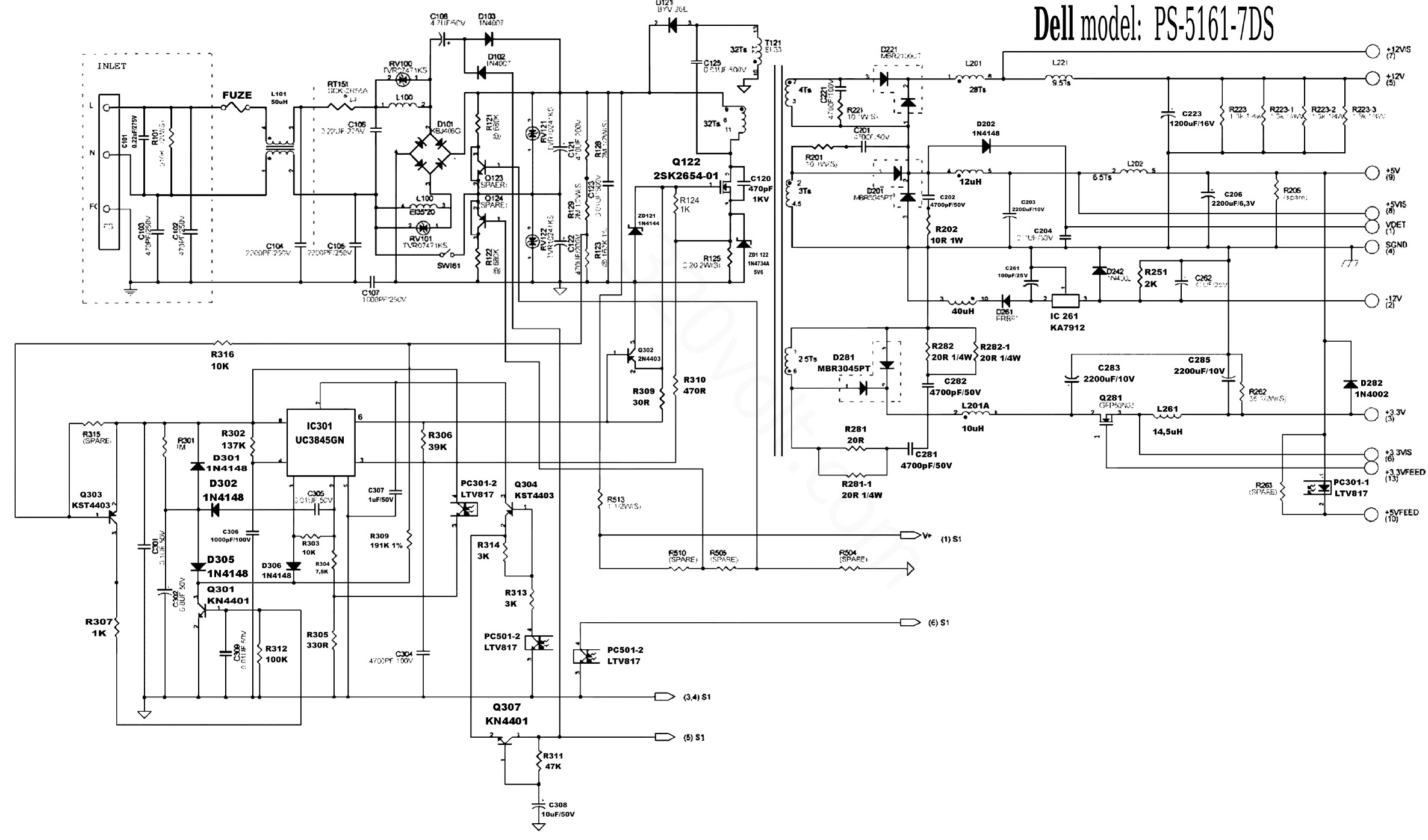
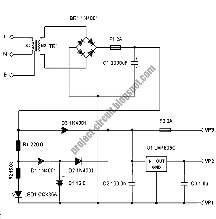
The circuit drawn pertains to a regular industrial UPS (Uninterruptible Power Supply), which shows how the batteries take control during an outage in electrical supply or variation beyond the normal limits of the voltage line, without disruption on the operation providing a steady regulated output (5 Volts by LM7805) and an unregulated supply (12 Volts).
Free Project Circuit Diagram Basic Uninterruptible Power Supply Circuit
A basic UPS circuit will have the following fundamental stages: 1) An inverter circuit. 2) A Battery. 3) A battery charger circuit. 4) A changeover circuit stage using relays or other devices such as triacs or SSRs. Now let's learn how the above circuit stages may be built and integrated together for implementing a reasonably decent UPS system.
Uninterruptible Power Supply Circuit Diagram The circuit drawn pertains to a regular
The uninterruptible power supply (UPS) schematic. Figure 1 shows the circuit. The backup power source for this design was a preloved car battery purchased from a scrapyard for £20. The LTC3789 is a four switch buck-boost converter that provides a constant 12 V supply, with extremely high efficiency, from an input that could be above or below.
